
Townhouse structure for a lift: 8 points to settle at the drawing stage
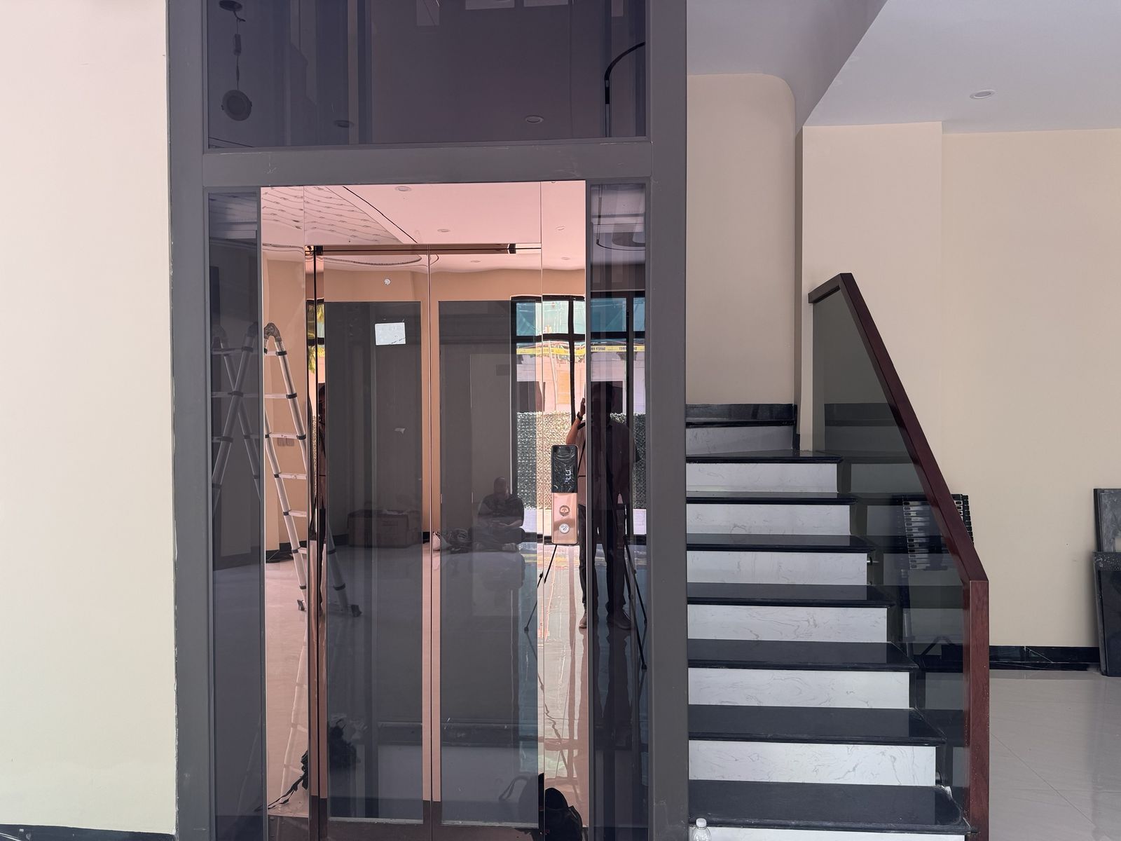
- Why the lift must be in the structural drawings
- Shaft: clear dimensions and plumbness
- Shaft walls: concrete, braced brick or steel frame
- Pit: depth, pit floor and waterproofing
- Shaft top: OH, lifting hook and ventilation
- Landing door openings and finished floor levels
- Power supply and earthing
- Checklist before handing the shaft to the lift installer
- Frequently asked questions
In a townhouse the lift usually sits in a shaft only 1.4 – 1.8 m wide, running through 4 – 6 floors. A few centimetres off in the shaft, a few dozen millimetres short in the pit or a forgotten lifting hook can mean demolition, a different lift line or a smaller cabin. This article covers 8 structural items that ASAHI engineers always ask owners and designers to settle at the drawing stage.
1. Why the lift must be in the structural drawings
A lift is equipment fitted into a building, but the conditions for installing it lie in the construction: the shaft, pit, shaft top, rail bracket fixing points and landing doors. Every manufacturer and lift line has its own requirements, so the safest approach is to choose the lift line and load before finalising the structure, then give the structural engineer the supplier's shaft requirement drawing as an input.
Vietnam's current lift standards are the TCVN 6396 series (equivalent to Europe's EN 81), in which TCVN 6396-20:2017 corresponds to EN 81-20:2014 for passenger lifts. Home lifts also have their own regulation, QCVN 32:2018/BLĐTBXH. These documents set many clearances and safety spaces that directly affect shaft dimensions.
2. Shaft: clear dimensions and plumbness
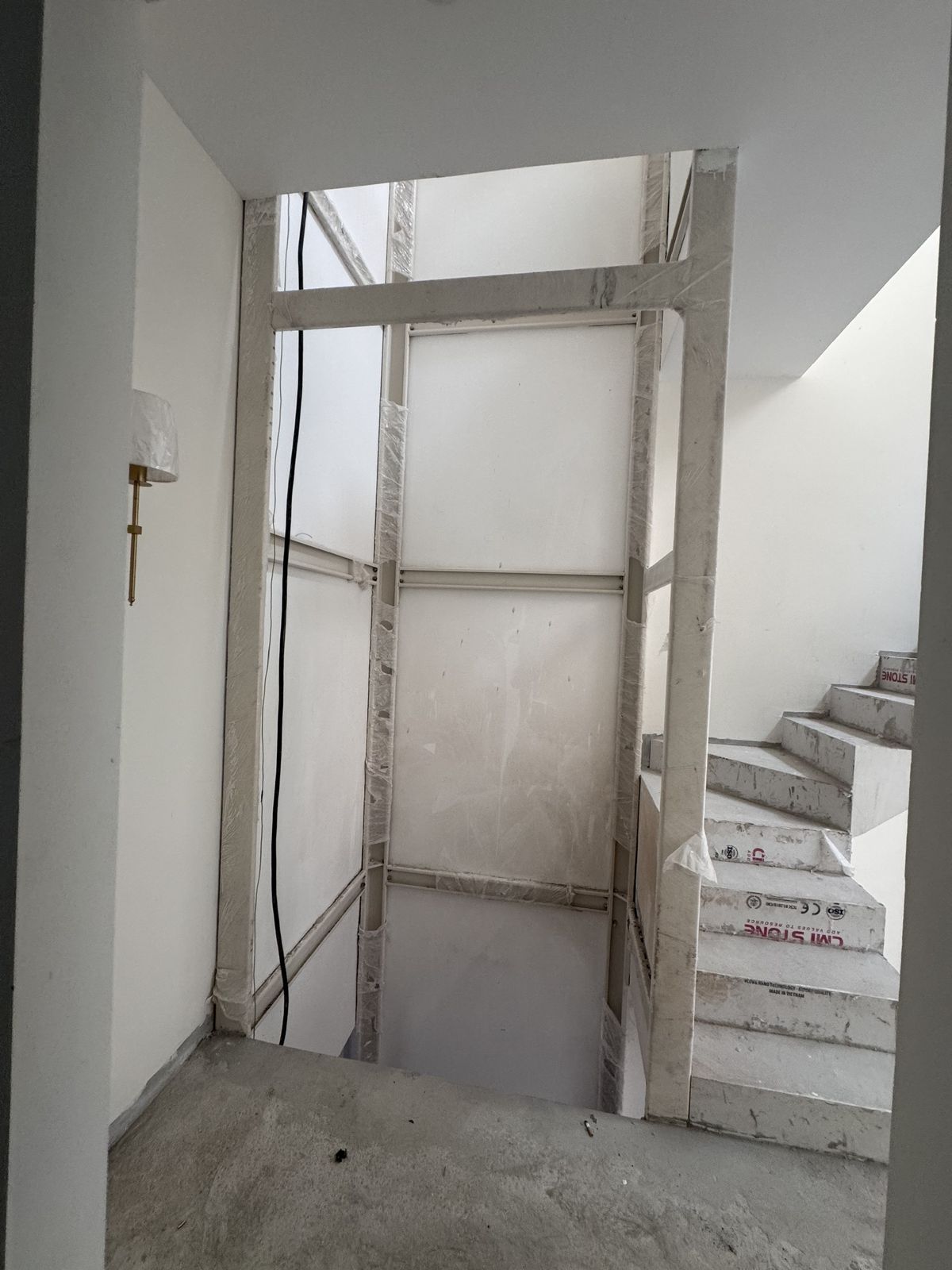
The dimensions on a lift drawing are clear dimensions after plastering, not grid lines or brick faces. Many shafts are built to the drawing, but after plastering and cladding lose 15 – 25 mm on each side and end up undersized.
- Allow a tolerance: design the shaft about 20 – 30 mm larger than the minimum in each direction.
- Plumbness: the shaft must be straight over its full height. A "twisted" shaft or floors that are offset are a common reason the cabin has to be made smaller.
- Cabin-to-shaft clearance: QCVN 32:2018 requires at least 20 mm between any projecting part of the cabin and the shaft wall, and no more than 30 mm horizontally between the car sill and the landing sill. An out-of-square shaft makes it hard to meet both at once.
The table below gives reference sizes for machine-room-less traction home lifts; exact figures depend on the lift line and door type.
| Rated load | Cabin (R × S, mm) | Minimum shaft (W × D, mm) | Pit (mm) | OH (mm) |
|---|---|---|---|---|
| 250 kg | 900 × 1.000 | 1.400 × 1.400 | 400 – 500 | from 3,300 |
| 350 kg | 1.000 × 1.100 | 1.500 × 1.550 | 450 – 550 | from 3,400 |
| 450 kg | 1.100 × 1.250 | 1.650 × 1.700 | 500 – 600 | from 3,600 |
ASAHI reference figures for traction home lifts; counterweightless, screw-drive and aluminium-frame lifts have different requirements.
3. Shaft walls: concrete, braced brick or steel frame
The cabin guide rails are fixed to the shaft wall with brackets spaced up the height of the shaft, so the wall must be rigid at these points.
- Reinforced concrete walls: best for traction lifts, with expansion bolts fixed directly.
- Brick walls: acceptable if there are concrete tie beams at the rail bracket levels, usually at every floor and mid-floor. Never fix rail brackets into hollow bricks.
- Modular steel or aluminium frame: used for glass lifts, renovations and outdoor shafts. The supplier designs the frame; the building only needs a floor strong enough at the frame base.
4. Pit: depth, pit floor and waterproofing
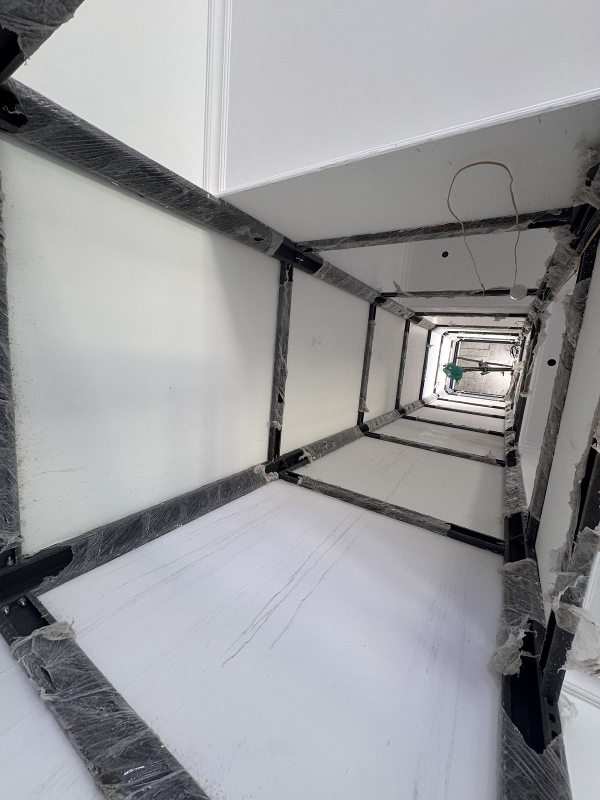
The pit is the part of the shaft below the lowest floor level; it houses the buffers and creates the safety space under the cabin. For home lifts under QCVN 32:2018, with the cabin resting on the mechanical stop device, a clear block of at least 1,370 × 450 × 600 mm or 600 × 500 × 1,290 mm must remain under the cabin.
- Load-bearing pit floor: buffers transfer forces to the pit floor if the cabin strikes them. The lift supplier provides the reactions at the buffer and rail bases so the structural engineer can design the pit slab.
- Waterproofing: standing water in the pit is the most common defect in townhouses, especially on low-lying land. Waterproof it like a water tank, with wall sleeves where needed, and keep floor drains from flowing towards the shaft.
- Shallow pit: if the pit cannot be dug deep (thick raft foundation, renovation), consider a shallow-pit line such as a screw-drive lift (50 – 100 mm) or a solution for existing buildings under TCVN 6396-21.
5. Shaft top: OH, lifting hook and ventilation
OH (overhead) is the distance from the finished floor of the top landing to the shaft ceiling. It must be enough to leave a safety space on top of the cabin even if it travels past the top floor. Machine-room-less traction home lifts typically need about 3,300 mm or more; screw-drive and some special lines need less.
- Lifting beam (hook): provided in the shaft ceiling to hang a hoist when installing the machine and rails. Its position and load follow the supplier's drawing.
- Ventilation: under EN 81-20, shaft ventilation is the responsibility of the building designer; the manufacturer provides heat output data for the equipment. In a townhouse, a vent or extract fan at the top of the shaft helps the controller and machine last longer in hot weather.
- Rain-proof shaft roof: shafts on a roof structure or terrace must be fully covered so no water leaks onto the machine.
6. Landing door openings and finished floor levels
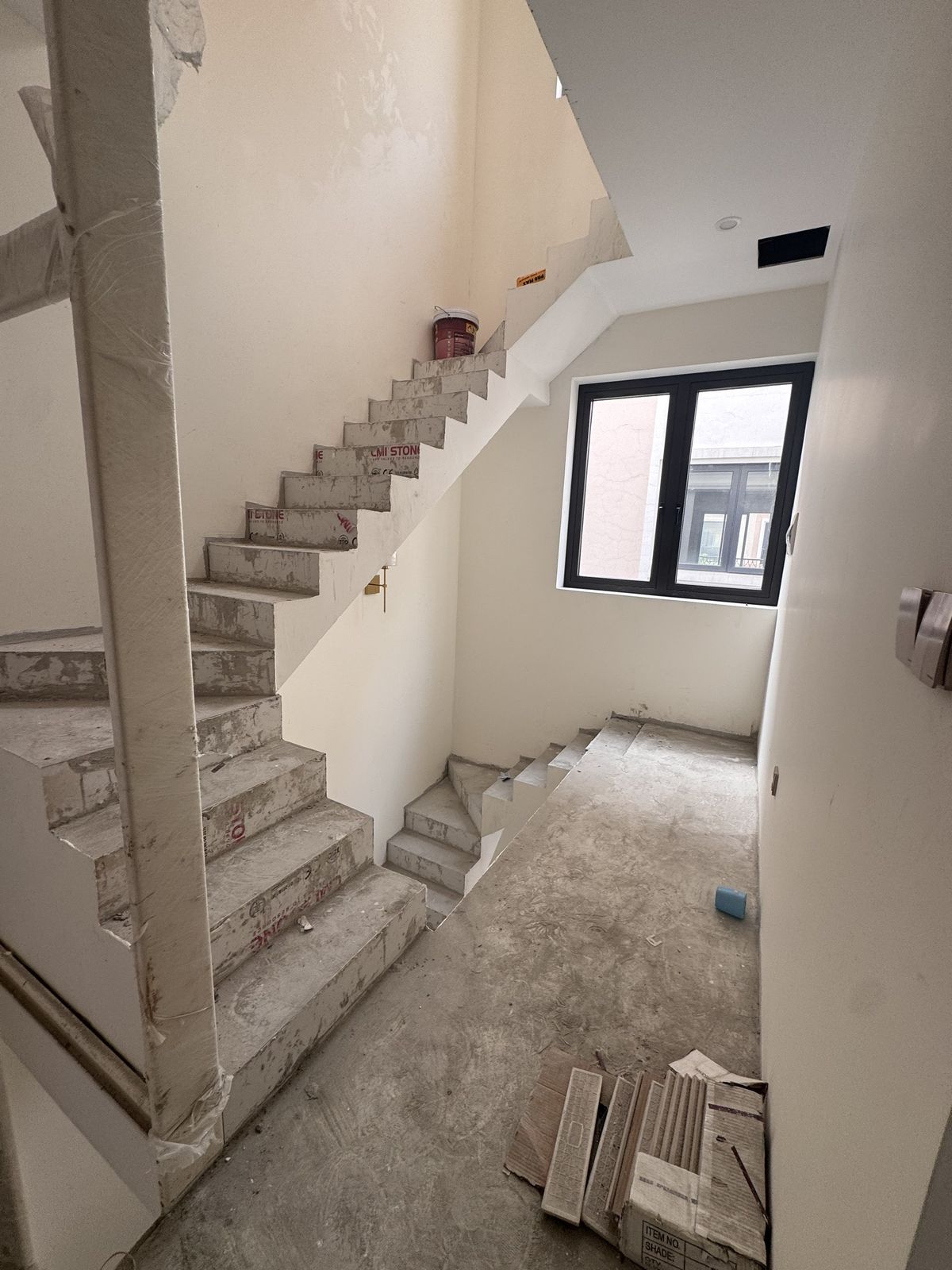
Landing door openings must have the right width, height and position relative to the shaft centreline. Even more important is the finished floor level on each floor: landing sills are set to it. If stone is later laid thicker than planned, the sill ends up below the floor surface, creating a trip hazard and requiring rework. Agree the floor finish thickness before landing doors are installed.
7. Power supply and earthing
- Run a dedicated supply from the main board to the lift controller location (top of the shaft or beside the top landing door), with its own circuit breaker.
- Decide in advance between 220 V single-phase and 380 V three-phase for the lift line; low-capacity home lifts can usually run on single-phase.
- Provide a compliant earth conductor and shaft lighting. EN 81-20 requires minimum lighting levels in the shaft (50 lux at working positions on the car roof and in the pit).
8. Checklist before handing the shaft to the lift installer
- Clear shaft dimensions as drawn on every floor, after plastering
- Shaft plumb, with no ledges or beams projecting into it
- Pit deep enough, flat, dry and waterproofed
- Enough OH, with a lifting hook in the shaft ceiling
- Tie beams at rail bracket levels (for brick walls)
- Landing door openings to size, with finished floor level marks
- Dedicated power supply, circuit breaker and earthing ready
- Shaft clean, with safety barriers at landing openings
ASAHI engineers work on site from the structural phase at Vinhomes Ocean Park and Global Gate, checking shafts and issuing written correction requests before installation. If you have architectural drawings, send them and ASAHI will check the lift shaft free of charge.
Frequently asked questions
What is the minimum shaft size for a townhouse?
For a 250 – 350 kg traction home lift, the clear shaft is usually about 1,400 × 1,400 mm to 1,500 × 1,550 mm. Counterweightless and screw-drive lifts can fit smaller shafts.
Can a lift be installed in a brick shaft?
Yes, if there are concrete tie beams at the rail bracket levels. Never fix rail brackets directly into hollow bricks.
What if the pit is not deep enough?
Choose a shallow-pit line (such as a screw-drive lift), or a solution for existing buildings under TCVN 6396-21 with devices that protect the safety spaces. The lift supplier must survey the site to choose the option.
Who is responsible for shaft ventilation?
Under EN 81-20, the building designer is responsible for shaft ventilation; the lift supplier provides heat output data for the equipment.
- QCVN 32:2018/BLĐTBXH – Occupational safety for home lifts (Hệ thống pháp luật, in Vietnamese)
- Clearance between the pit floor and the cabin of a home lift (Thư viện Pháp luật, in Vietnamese)
- Circular 12/2021/TT-BLĐTBXH – list of applicable TCVN 6396 standards (LuatVietnam, in Vietnamese)
- KONE – EN 81-20 Safety Standard Fact Sheet
- Cibes Lift Vietnam – 5 points for the structural drawings of a house with a lift, in Vietnamese
This article is for general reference. Figures for each project follow the site survey and the lift supplier's drawings; regulations may be updated, so owners should check the original texts.

Engineers who survey and install home lifts at Vinhomes Ocean Park and Vinhomes Global Gate.